Place of Origin: | CHINA |
---|---|
Brand Name: | Tenkai |
Certification: | ISO9001-2015 |
Model Number: | UFP10 |
Minimum Order Quantity: | 1 wooden package |
Price: | Negotiate/Competitive |
Packaging Details: | Wooden Box Package |
Delivery Time: | Within 12 days |
Payment Terms: | L/C, T/T, D/P at sight |
Supply Ability: | 180pcs/Day |
Material: | Copper/Stainless Steel | Copper Design Temperature: | -196 ℃-225 ℃ |
---|---|---|---|
Copper MAX Design Pressure: | 4.5 Mpa | Stainless Steel Design Temperature: | -196 ℃-550 ℃ |
Stainless Steel Max Design Pressure: | 2.5 Mpa | Connection Mode: | Male Thread , Female Thread, Flange, SAE Flange, Soldering |
Warranty Period: | One Year | Structure: | Plate Heat Exchanger |
Weld: | Brazed | ||
Highlight: | Unequal Flow Path Heat Exchanger Brazed,Unequal Flow Boiler Plate Heat Exchanger,Industrial Grade Boiler Plate Heat Exchanger |
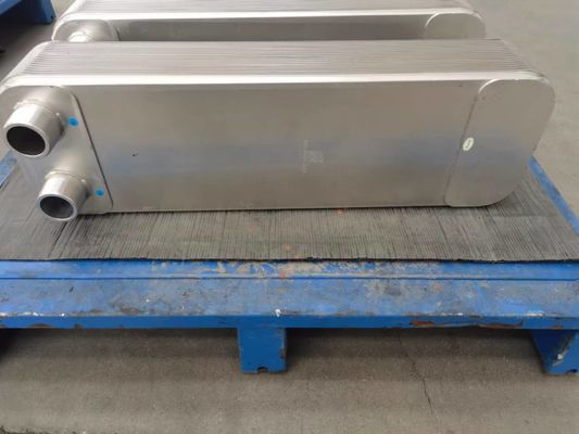
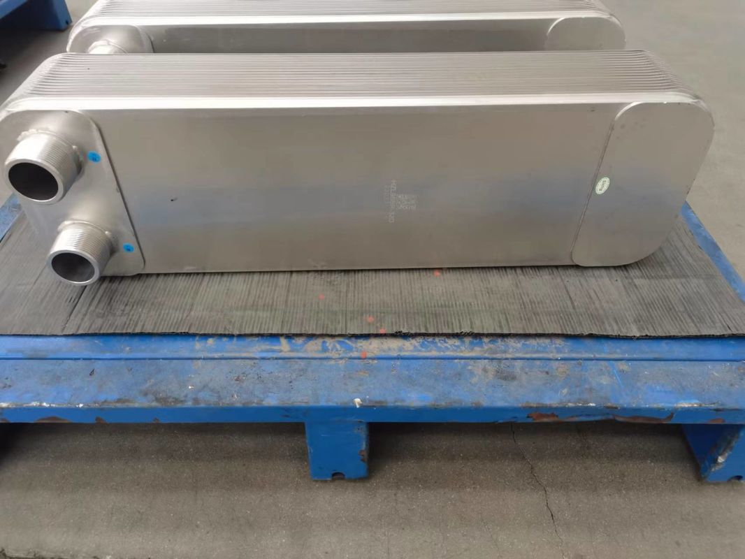
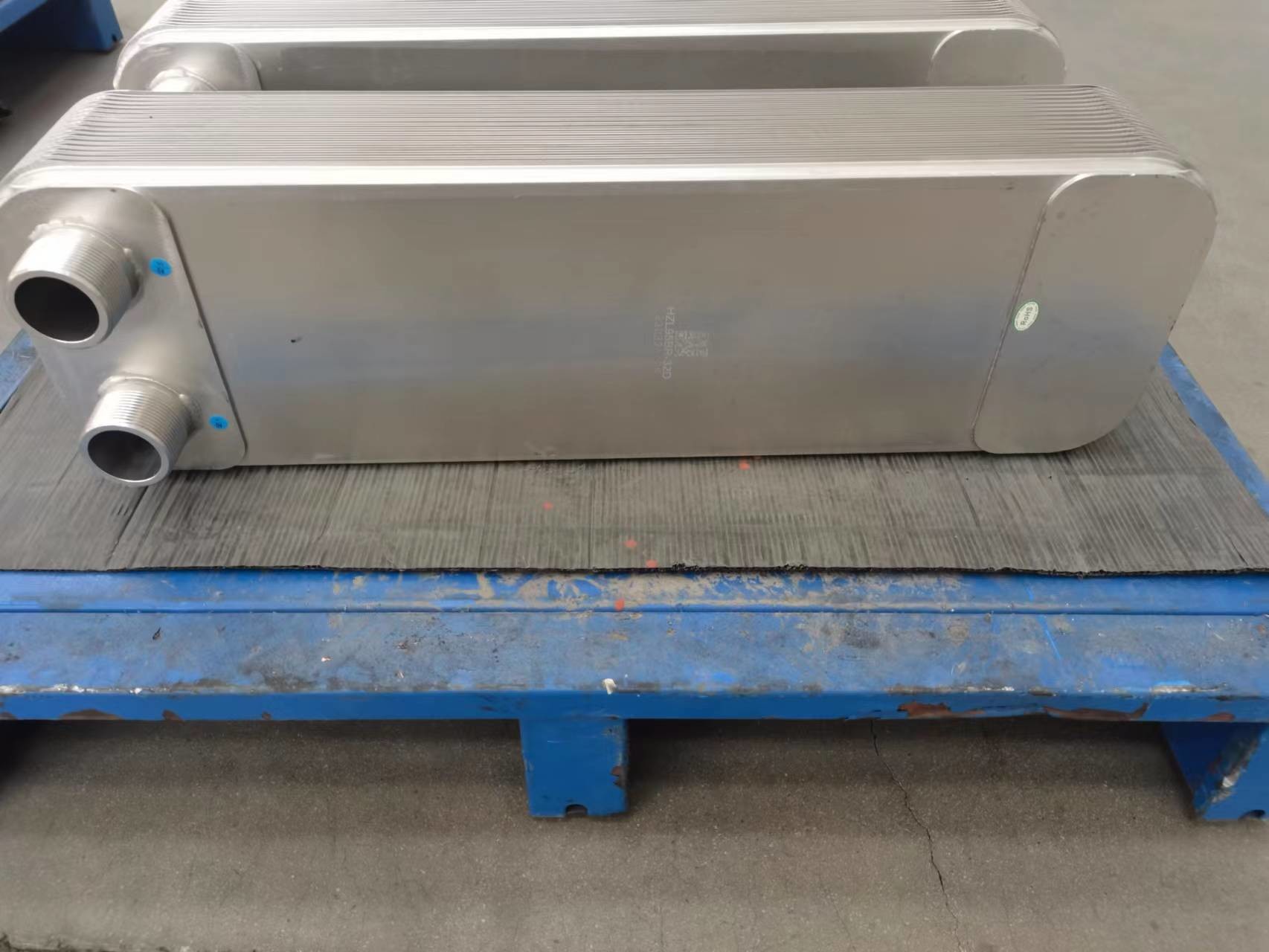
BPHE Reduced Fouling And Scaling Unequal Flow Path Boiler Plate Heat Exchanger
Product Introduce :
Unequal Flow Path is the one kind of innovative , patent which incoming from Brazed Heat Exchanger , this kind of unequal flow path signify it is different on cold and heat for path volume . It is beneficial to take advantage of reasonable pressure drop on two flanks , If there is different flow or different fluid properties , for example oil and water , or different reasonable pressure drop needed on two flanks . Then , optimized heat transfer , so as to make the quantity of heat exchanger plate in unit reduce to the minimum , in some cases , the quantity of heat exchanger under the same load max reduce 25% . The path volume of primary side is 25% larger than secondary side .
It is a specific type of heat exchanger design that allows for different flow rates or flow paths for the two fluids being exchanged. In an unequal flow path BPHE, the channels or passages for the hot and cold fluids are not symmetrical, meaning that one fluid may have a longer or narrower flow path compared to the other fluid.
Characteristics and benefits of unequal flow path brazed plate heat exchangers:
Flow Rate Optimization: Unequal flow path BPHEs enable the optimization of flow rates for each fluid to meet specific requirements. By adjusting the flow path dimensions, the heat exchanger can be tailored to achieve the desired heat transfer performance and temperature differentials between the fluids.
Enhanced Heat Transfer Efficiency: The unequal flow path design allows for enhanced heat transfer efficiency by optimizing the velocity and residence time of the fluids. This can result in improved heat transfer coefficients and overall system performance.
Temperature Approach Control: Unequal flow path BPHEs can help control the temperature approach, which refers to the temperature difference between the hot and cold fluids at the exchanger's outlet. By adjusting the flow paths, the temperature approach can be minimized, leading to more efficient heat transfer and reduced energy consumption.
Flexibility in System Design: The unequal flow path design provides flexibility in system design, allowing for customization based on specific application requirements. It enables the heat exchanger to be tailored to handle different flow rates, fluid properties, and desired heat transfer performance.
Reduced Fouling and Scaling: The unequal flow path configuration can help mitigate fouling and scaling issues. By optimizing the flow rates and velocity distribution, it reduces the likelihood of deposits forming on the heat transfer surfaces, leading to improved operational efficiency and longer maintenance intervals.
Compact and Space-Saving: Like other brazed plate heat exchangers, unequal flow path BPHEs have a compact and space-saving design due to the stacked plate arrangement. This makes them suitable for installations where space is limited or when a high heat transfer surface area is required within a small footprint.
Wide Range of Applications: Unequal flow path BPHEs find applications in various industries that require efficient heat transfer with different flow rates, such as HVAC systems, industrial processes, refrigeration, and district heating/cooling networks.
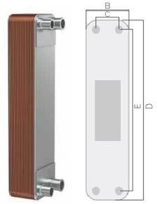
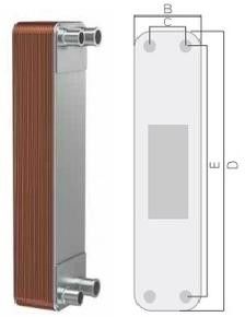
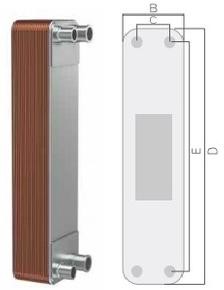
TYPE | B(mm) | C(mm) | D(mm) | E(mm) | THICKNESS(mm) | WEIGHT(Kg) | MAX FLOW (m3/h) | DESIGN PRESSURE(Mpa) |
UFP 10 | 77 | 42 | 155 | 119 | 9+1.25N | 0.28+0.027N | 4 | 3/4.5 |
UFP 20A | 93 | 40 | 323 | 269 | 9+1.5N | 1+0.09N | 8 | 3/4.5 |
UFP 42A | 121 | 68 | 332 | 279 | 10+1.53N | 2.05+0.11N | 18 | 3/4.5 |
UFP 62FA | 120 | 63 | 527 | 470 | 10+1.98N | 2.379+0.18N | 18 | 3/4.5 |
UFP 62FB | 120 | 63 | 527 | 470 | 10+1.98N | 2.379+0.18N | 18 | 3/4.5 |
UFP 95FA | 182 | 92 | 609 | 519 | 12+2.05N | 15+0.36N | 42 | 3/4.5 |
UFP 95FB | 182 | 92 | 609 | 519 | 12+2.05N | 15+0.36N | 42 | 3/4.5 |
Workshop :
Test Area :
Picture :